English

Why Inline Transducers? Precision for High-Pressure Systems
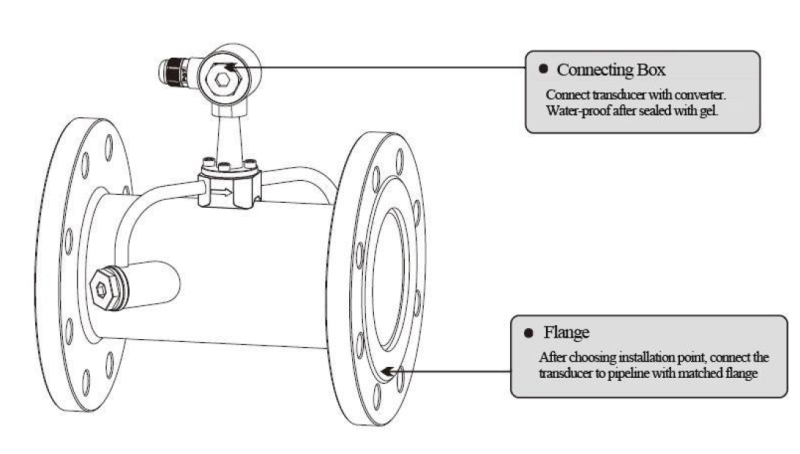
Inline transducers for the OUF Series deliver unmatched accuracy (±0.5%) in high-pressure (up to 4.0MPa) and high-temperature (160°C) applications. Unlike clamp-on or insertion models, they integrate directly into pipelines via flanges, eliminating signal loss from pipe walls. This guide covers flange welding, alignment, and leak-proof sealing for permanent installations.
Tools and Materials Required
• Pipe Cutting Saw: For precise cuts on steel, PVC, or composite pipes.
• Companion Flanges: Match the transducer’s flange rating (e.g., ANSI 150#, PN16).
• Alignment Rods: Ensure flanges are parallel and coaxial.
• Torque Wrench: Tighten bolts evenly (recommended torque: 30–50 Nm).
• Welding Equipment: TIG/MIG welder for steel pipes.
• PTFE Gaskets: High-temperature sealing
Step 1: Pipeline Preparation
1. Measure and Mark:
o Cut the pipeline to a length of transducer length + 2x gasket thickness + 10mm (e.g., 320mm for a 300mm transducer).
o Deburr cut edges to prevent flow turbulence.
2. Tack Weld Flanges:
o Position companion flanges on both pipe ends using alignment rods.
o Tack weld at 3–4 points to hold flanges in place.
Step 2: Welding Flanges
1. Full Penetration Welds:
o Weld flanges in segments, alternating sides to minimize heat distortion.
o Grind welds smooth to avoid crevices that trap debris.
2. Cooling Phase:
o Allow welds to cool naturally—quenching weakens joints.
Step 3: Installing the Inline Transducer
1. Gasket Placement:
o Position PTFE gaskets between flanges and transducer.
2. Bolt Tightening Sequence:
o Follow a star pattern to distribute pressure evenly.
o Torque bolts to 30 Nm initially, then 50 Nm in three passes.
Steps 1–4: Alternating bolt sequence for uniform sealing.
3. Alignment Check:
o Use a straightedge across flanges—max misalignment: 1mm per 100mm diameter.
Step 4: Signal Cable Connection
1. Wiring:
o Connect upstream (white/red) and downstream (green/black) transducer wires to the OUF-W converter.
o Ground shielding at the converter’s GND terminal.
2. Sealing:
o Apply waterproof gel to cable glands (IP68 rating).
Step 5: Leak Testing and Signal Validation
1. Hydrostatic Test:
o Pressurize the system to 1.5x operating pressure. Check for leaks at gaskets.
2. Signal Verification:
o Navigate to M90: Signal strength >80.0 and Q >70.
o Confirm flow direction matches physical installation (M00/M01).
Common Pitfalls
• Over-Tightening Bolts: Crushes gaskets, causing leaks. Use a torque wrench.
• Misaligned Flanges: Creates uneven flow profiles. Re-cut the pipe if misalignment >2mm.
• Ignoring Thermal Expansion: For steam lines, allow 5mm gap for flange expansion.
Ensure leak-free installations! Get in touch with our certified technicians for complex high-pressure systems!
Next in the Series
In Article 8: Configuring OUF-W Ultrasonic Flowmeters, we’ll explore parameter setup, alarm configuration, and MODBUS integration for seamless SCADA connectivity.

Please contact us for free quotation by form below. We promise the quickest response within 24 hours: